OTA Application

Our Core Technology | OHM+ Fast
(FTM), Automatic Calibration (AMC), Online
Recovery (ORC) and Group Testing(GPT), and its
scope of applications can be from chip level to
system level.
Times
Faster
Devices Under Test
Our Own Patent Certification
Core Technology: OHM+ Fast
Calibration method for a phased array of antennas (The above patent had transferred from national taiwan university)
The core technology can be extended: Our Own Patent Application
Fast calibration and diagnosis of phased array antennas by measuring a single-direction radiation power density without phase information
The core technology can be extended:Our Own Patent Application
Grouping system architecture for simultaneous multi-aips’diagnosis and calibration by measuring integrated radiations at a single field point wlan and bt group testing
The core technology can be extended:Our Own Patent Application
Fast rfic diagnosis and calibrations of output states by using a group test system architecture
Our Technical Difference
The ranking below is only for those three system structures.
| System Structure | Comparison | Remarks | |||
|---|---|---|---|---|---|
| Speed 1 | Accuracy | Cost | Others | ||
| Fast Measurement & Automatic Calibration(@Ohmplus) | High < 3 secs | Higher | Low | Calibrate Synchronously | # Complex Algorithm # Control interface is highly dependent |
| Quick Comparison (@Existing) | Middle < 5 mins | Low | Middle | Consistency Comparison with Golden Sample | # Golden sample is difficult to maintain # Unable to sync correction |
| Traditional Measurement | Slow> 4hours | Higher | Highest | Calibrate Synchronously | # Highest Cost |
Fast Measurement & Automatic Calibration
There are three bottlenecks in the development of MMW RF systems as temperature, process, and calibration. Among them, the calibration of the antenna system is the most important.
Then what is "calibration"? It must satisfy theoretically the following:
- Under the Near-Field system.
- It can measure completely the characteristics of array antenna.
- It can make sure of each antenna unit is working properly and not damaged.
- It can adjust the phase and amplitude of each antenna unit to the best combination.
The measurements of MMW array antennas or RF chips/modules are mostly compared with the golden sample to confirm whether those products meet the specifications. Although it was feasible, but for those defective products, they were only returned for reassembly and re-measurement or directly scrapped. However, our Fast Measurement & Automatic Calibration can make those defective products on the production line adjust to meet the specifications through our automatic calibration, thus greatly reducing costs and time. That is because, it doesn't need Golden Sample, and its speed of the error measurement for amplitude and phase is so fast, and the time to complete all antenna components’ calibrations is only under the second level. (Table 4).
| Near-Field Scan | Comparison Test | OHM+ Fast | |
|---|---|---|---|
| Pros | * To scan completely and obtain its characteristics * To obtain the distributions of amplitude & phase of the antenna surface via Fourier transform * To reduce the requirements of testing site | * Simple and Fast * No complex calculations | * Simple and fast * All antenna units can be fully opened * The measurement can be at operating temp. * Online Recovery is workable for damaged ratio is < 10%. * The Active Testing is measured. * The time of measurement & analysis is< 3 secs 3 |
| Cons | * Calculation process is very complex1 * Testing speed is very slow 2 * The time of analysis data is too long * The antenna under test must be calibrated * Only the radiation characteristics can be tested | * Lack of Far-Field conditions * It is failed to get correct data | * Need to calculate * Unable to obtain complete antenna characteristics 4 |
| Testing Items | * BFIC amplitude, phase calibration * BFIC dead zone * Antenna optimization * Antenna radiation pattern * Axial ratio * EIRP * G/T | * Pass and Fail * Gain * EIRP | * BFIC amplitude, phase calibration * BFIC dead zone * Antenna optimization * Axial ratio * EIRP * G/T * EVM * ACPR |
| Price | High | Very Low | Low |
Fast Codebook Reconstruction
- The new Codebook can be set immediately and rewritten into the MCU controlling the antenna.
- It can calibrate the errors of amplitude and phase for each antenna units.
- It can be adjusted if the direction of beamforming is offset.
- It can decrease the sidelobe of the antenna pattern and increase the antenna gain.
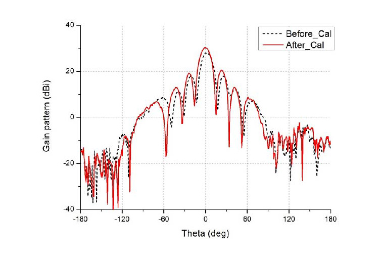
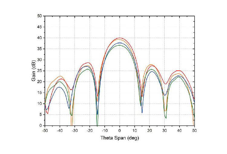
The measurement result as above made by our customer. In that figure, that black dotted line is calibrated by the Comparison Test, and the red solid line is calibrated by our Fast Measurement & Automatic Calibration.
From this figure, we can clearly see that the result of the red solid line is better than the black dotted line, because the gain of the red solid line is higher about 2dB than the black dotted line, and the Side-Lobe is also significantly lower. Although the traditional Comparison Test can achieve the purpose of calibration, the overall result is still not as good as Fast Measurement & Automatic Calibration of Ohmplus Technology Inc.
Online Recovery
In addition to calibrate the phase error, our Fast Measurement & Automatic Calibration can also find out the problematic array antennas and phase shifter units and recovery.
Furthermore, the numbers of failed array antenna elements are < 10%, the Online Recovery is immediate. But if the numbers of disabled antenna elements are>10%, it is necessary to consider the location of all disabled antenna elements. Usually, if they don't occur in the middle area of the array antenna, Online Recovery can do it.
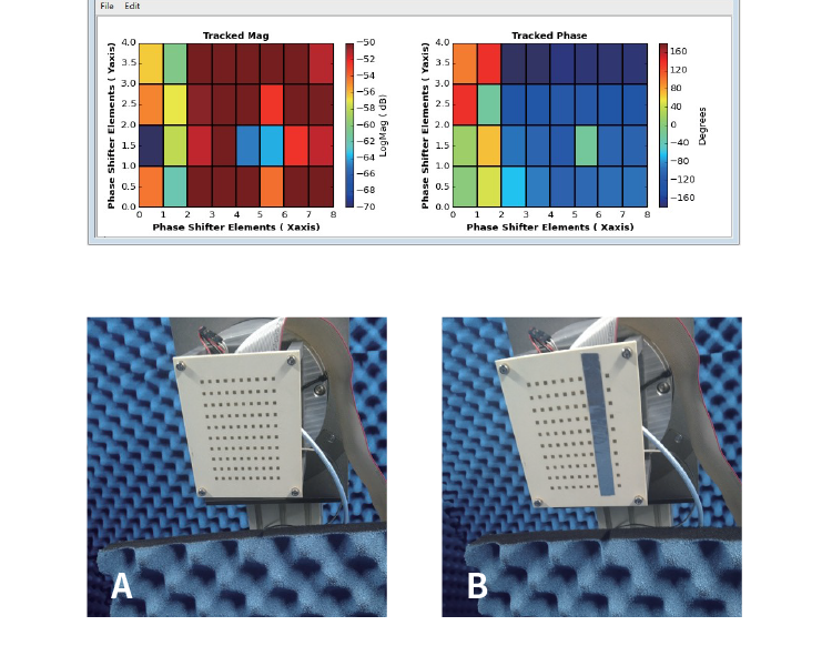
We do a control experiment to observe and compare the complete array radiation pattern without failure antenna elements (Figure .A) and the other one with failure antenna elements failure (Figure B). Figure 8 shows that there are eight antenna elements shielded by metal patches to simulate the failure condition.
The antenna radiation patterns of that above control experiment are measured and shown as above , and among them:
We can see the antenna radiation pattern is seriously distorted.
| Switching Testing | Parallel Testing | Group Testing | |
|---|---|---|---|
| Instrument | S-parameter : Network Analyzer EVM & BT : VSG & VSA | ||
| Measurement Method | Switch to Different Site | S-Parameter : Switch to Different Site EVM & BT : Parallel to Different Receiver | Group Testing |
| Measurement Speed | 1 | 2 | 3 |
| RF Path Loss | 2 | 3 | 2 |
| Calibration | 3 | 3 | 3 |